Category: Iacdrive_blog

UPS systems commissioning test and inspection procedures

The UPS systems commissioning test and inspection procedures are to conform to;

• BS EN 50091-1:1993 – Specification for Uninterruptible Power Supplies (UPS). General and Safety Requirements, AND

• IEC 62040-3 (Draft Edition – 2) in particular the Efficiency test procedures outlined in its “Annexure-J”.

These procedures to include:

1. Visual Inspection:
a. Visually inspect all equipment for signs of damage or foreign materials.
b. Observe the type of ventilation, the cleanliness of the room, the use of proper signs, and any other safety related factors.

2. Mechanical Inspection:
a. Check all the power connections for tightness.
b. Check all the control wiring terminations and plugs for tightness or proper seating.

3. Electrical Pre-check:
a. Check the DC bus for a possible short circuit.
b. Check input and Bypass power for proper voltages and phase rotation.
c. Check all lamp test functions.

4. Initial UPS Startup:
a. Verify that all the alarms are in a “go” condition.
b. Energize the UPS module and verify the proper DC, walkup, and AC phase on.
c. Check the DC link holding voltage, AC output voltages, and output waveforms.
d. Check the final DC link voltage and Inverter AC output. Adjust if required.
e. Check for the proper synchronization.
f. Check for the voltage difference between the Inverter output and the Bypass source.
g. Perform full-load, step-load, and battery discharge tests using supplier furnished load bank.

Why your project failed?

I have contracted with lots of different groups and moving within the same company to save failed projects or project in trouble or impossible to implement and helped these groups to achieve company goal. What I have noticed is that less the managers or groups know less they realize more knowledge or experience can help them. Less they know, less they understand they need help because they don’t know what they need. They think they are just fine until it is too late and a group or company goes under because of it.

I give you an example of one of the project I worked on at Nortel. I was assigned to write project specification for a product working with a director group with 100 designers and testers. During my research to get information to write the product specification I discover deficiency in the hardware they wanted to use that would cause the system reliability and availability unacceptable to the customer and did not meet customer requirement. I proposed design change in one of the interface card and firmware used in the system. The management did not agree with me on this item so I refused to write the specification the way they want it to not expose this deficiency. We had a large meeting with the president of the company with 20 people in that meeting looking at two different presentation to see if they need to change direction or stay on course and move me out of the way to another project activity. I am not the greatest in politics and making things look good when they are not.

The result was that I was moved to different project for 1 year implementing and releasing one more product that made the company lots of money. After a year development, they complete the project and released it to the customer. The customer starts validating the product and had lots of the test cases failing in the area that I proposed to change.
This was a large project and lots of money involve. The customer rejected the product and they went back on the drawing board after getting lots of this equipment on order for this project. The management came back to me and one of my team members to come back to the team and help.

Me and my team member both having experience over 15 years at that point came back and have a solution designing a new complex interface card with microcode firmware and some software to save the project. I and he had to work for 4 months for day and night having design review between two of us at 3 am in the cafeteria to get it done (defining specification to validated working product).

This project was completed and customer accepted this solution. The director group was dismantled and all people in the group were laid off and absolved in other groups in the company and some in the same group. The management groups were smart people with good intention, they were with software background and good intention for the project. They just did not have the knowledge and background to manage the system and hardware level because of lake of knowledge and experience in that area.

You see this in lots of companies when a software designer or manager is successful in their area, they get promoted and manage groups that are out of their area and lots of time they destroy groups or project because of not having the background to identify good or bad direction to go. You will always have engineers to not agree with each other and managements have to make decision to go one way or another. The wrong decision in these cases can destroy a project or company. Not all engineers can present a case in 1 hour to sell you their point of view, Remember they are not lawyer or sales man, they are engineers. So what do you do, Follow the sales man or lawyer to save your project or the reason to drive your decision and if you don’t have the knowledge or experience to lesson to the reason then you will make the wrong decision.

What if

Many years ago we used to call this the “what ifs?”. Part of the design phase is when we model what we think the system is meant to do. Just as important is how the system is meant to react when things are not going well, the abnormal situations or what ifs?

Your client will tell you how their machine or process works, well he will describe how he thinks it works. This is OK as a starting point but we need to consider the scenarios of “what If” something goes wrong? Scenarios is also a good word as scenarios paint a situation that can be described to the customer for his comment.

For example on a compressor control project what if the lube oil pump fails on the compressor, how do we alarm this to the Operator, should we trip the compressor or do we start the back-up oil pump (if there is one). As you look at the system you can pick out various components and generate likely scenarios that you can discuss with the client. Using this approach gives more of a real world feel to your client meetings that are likely to generate a deeper insight into how the system is meant to work.

All scenarios do not have to be centered around abnormal situations but can also relate to things that need to be considered as part of normal operation. For example we might look at how a duty/standby pump system works? One scenario might relate to duty pump failure but another scenario might consider rotating the duty and standby pumps to even out wear and tear? You might also have manual mode and auto mode scenarios to consider?

What you have to remember is that most clients are not control systems experts. They might and probably will struggle with flow charts or any other pseudo code expression type formats that describe how you think the client’s system is meant to work? You have to tailor your approach to match your audience and that is also very important when you produce your documentation, you do not want to lose valuable information just because the client doesn’t fully understand what you are trying to tell him? Also make sure that you spend time with your client. Walk the client through your design, do this face to face as much as possible and do it more than once! Getting feedback on a regular basis helps to eliminate the dreaded word “REWORK”! Also taking this partnership approach builds a good relationship with your client.

For the machine builders your client might be in your own company? Remember same company or not they are your client and your success in no small way depends on your relationship with them.

Add the modes of operation and abnormal situations to your system model and develop the methods of how you will flag these situations to the Operator and Maintenance Engineer. Alarm Management is dealt with by EEMUA 191. If you do nothing else then read this document it will help you to set up alarm workshops, alarm reviews, alarm prioritization and rationalization and how to develop an effective alarm management structure for your system.

Benefits of Having products and services in the same company

Having products and services in the same company can either be treated as an opportunity or as a constraint. I strongly believe that having services and products in the same company should be treated as an opportunity, and that any potential constraints should be eliminated.

Here are the things that I have learned.

First: Never limit the product sales to the capacity of your service organization:
I see some companies that develop products that are so great that they want to be the only organization delivering, implementing and maintaining them. They believe that the products are a competitive advantage that will allow them to dominate the services market. This almost always fails; your example from Xerox is one of many. One of two things tend to happen: Either the product does not reach its full market potential due to limited services capacity, or the product organization limits their innovation and product development so that it can continue a lucrative services business. Both may be good short term, but fails on a longer term basis.
My recommendation is that companies that have both products and services should allow their products to be delivered, implemented and maintained by other companies that compete with themselves in the services market.

Second: Never limit the services that you offer to the products that you have in your own portfolio:
Service organizations are typically focused on delivering, implementing and maintaining solutions for their customers. They deliver more than just the product. If you limit the services to only focus on the products in the in-house portfolio, then you are either going to miss opportunities to sell services or you are going to get a portfolio that is too broad. Neither of them is good.
My recommendation is that companies that have both products and services should allow their services organization to deliver products from everywhere, even products that directly compete with the products in their own portfolio. This will ensure that the services organization stays competitive.

Third: Leverage the synergies between products and services:
You may ask “why have both products and services in the same organization if they need to be kept separate?”. The answer lies in the synergies. Companies need to create a culture where the product and services organizations can collaborate even though they are independent. Good organizations can make good decisions about when to expand their own portfolio and when to solve the same customer problems through services and/or third party products. I have seen great innovations come from organizations that master this.

Having products and services in the same organization creates a great foundation for innovation. The key to success is to have the right company culture.

System operation

Our PSA unit (meaning Pressure Swing Adsorption) uses 5 adsorption vessels. The process itself is a batch process, but in order to run in a continuous process plant, each of the 5 vessels can complete all the adsorption process but at the same time, each of them is in a different status of the sequence (i.e. gas in, gas out, adsorption, pressurizing, depressurizing, cleaning, etc). The sequence is mainly controlled by time and pressure condition in each step of the sequence, by managing several valves (I think 5 by vessel, but I’m not sure right now).

Panel operator experienced some problems with valve 1 (gas entry) in vessel 2 because it should open but immediately it received the close command. Instruments technician check that orders coming from the DCS were OK, and also check the valves by injecting the open order, so, they and operation staff concluded that “the program has some kind of problem”.

Some time ago, I spent a lot of time studying the operation manual of this unit and the code written to control it and I wrote a document merging both knowledge. In page 9, I described a condition (an exclusive pressure difference between vessel and gas coming in the vessel) avoiding valve 1 opening during adsorption stage. I explained this condition to operation staff and they confirm that the values were right and that the excessive delta P really exist so, the decided to check back the valve 1 (already checked), discovering a problem (the stem moved, but the disk not).

Conclusion:
– If operation staff know properly the process, they know about this condition, but this could be solved with a properly designed HMI (i.e. including and alarm indicating “valve 1 closed by excessive deltaP”).
– The initial inspection of the valve didn’t show anything wrong, but stem and disk were disconnected.
– If we didn’t dig into the code, this problem, solved in less of an hour could take several hours.

DC Drives Parameter Setting / Programming

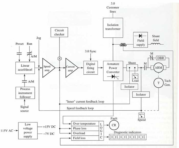
Programming parameters associated with DC drives are extensive & similar to those used in conjunction with AC drives. An operator’s panel is used for programming of control setup & operating parameters for a DC drive.

SPEED SETPOINT
This signal is derived from a closely regulated fixed voltage source applied to a potentiometer. The potentiometer has the capability of accepting the fixed voltage & dividing it down to any value, For example, 10 to 0 V, depending on where it’s set. A 10-V input to the drive from the speed potentiometer corresponds to maximum motor speed & 0 V corresponds to zero speed. Similarly any speed between zero & maximum can be obtained by adjusting the speed control to the appropriate setting.

SPEED FEEDBACK INFORMATION
In order to “close the loop” & control motor speed accurately, it’s necessary to provide the control with a feed back signal related to motor speed. The standard method of doing this in a simple control is by monitoring the armature voltage & feeding it back into the drive for comparison with the input setpoint signal. The armature voltage feedback system is generally known as a voltage regulated drive.

A second & more accurate method of obtaining the motor speed feedback information is from a motor mounted tachometer. The output of this tachometer is directly related to the speed of the motor. When tachometer feedback is used, the drive is referred to as a speed regulated drive.

In some newer high-performance digital drives, the feedback can come from a motor-mounted encoder that feeds back voltage pulses at a rate related to motor speed.

These pulses are counted & processed digitally & compared to the setpoint, an error signal is produced to regulate the armature voltage & speed.

CURRENT FEEDBACK INFORMATION
The second source of feedback information is obtained by monitoring the motor armature current. This is an accurate indication of the torque required by the load.

The current feedback signal is used to eliminate the speed droop that normally would occur with increased torque load on the motor & to limit the current to a value that will protect the power semiconductors from damage. The current-limiting action of most controls is adjustable & is usually called current limit or torque limit.

MINIMUM SPEED
In most cases, when the controller is initially installed the speed potentiometer can be turned down to its lowest point & the output voltage from the controller will go to zero, causing the motor to stop. There are, how ever, situations where this is not desirable. E.g.,, there are some applications that may need to be kept running at a minimum speed & accelerated up to operating speed as necessary. The typical minimum speed adjustment is from 0 to 30 percent of motor base speed.

MAXIMUM SPEED
The maximum speed adjustment sets the maximum speed attainable. In some cases it’s desirable to limit the motor speed (and machine speed) to something less than would be available at this maximum setting. The maximum adjustment allows this to be done.

IR COMPENSATION
Although a typical DC motor presents a mostly inductive load, there is always a small amount of fixed resistance in the armature circuit. IR compensation is a method used to adjust for the drop in a motor’s speed due to armature resistance. This helps stabilize the motor’s speed from a no-load to full-load condition. IR compensation should be applied only to voltage-regulated drives.

ACCELERATION TIME
As its name implies, the acceleration time adjustment will extend o

How to improve troubleshooting techniques?

The guy asked for suggestions on how to improve troubleshooting techniques. I mentioned this earlier as a “suggestion” for starters but the idea got lost in all the complaining and totally irrelevant responses like the one above.

Proper lay out of inputs and outputs and a “Troubleshooting guide” or flow chart. I have an Aris cablem modem and Netgear wireless router for internet If loose Internet service I can do three things.

A. Pick up the phone, call tech support and wait two days for someone to show up

B. Take them apart and ‘DIG INTO THE PROGRAMMING”

C. Read the instructions someone took the time to write. Before I can get an output identified by the LEDs, I have to have the correct inputs identified by the LEDs. It’s a waste of time tearing in the “programming” over a loose cable connection somewhere. Same for the wireless router and a bad LAN cable connection or network service issue on the computer. I’m already familiar with the proper LEDs for normal operation. When one goes out it gives me an idea where to start looking before even opening up the instructions which I’ve downloaded in PDFs for quick access to their “troubleshooting” guides. Maybe the service is off line – there is an LED for that. No TVs either, no service or common upstream cable connection problem, no-brainier. The first thing a Xfinity service tech does is go outside and look for a signal at the house customer jack. It’s either in his cable or my house. Once their cable had to be replaced. It mysteriously got damaged right after AT&T dug a big hole in my backyard to upgrade their Uverse service – go figure.

In order to get something to operate output wise, you need a certain amount of inputs to get it. If you don’t have a particular output, then look at the trouble shooing guide and see what inputs are required for it. If there are four direct sensor inputs required for a particular output, group them together.

Grouping internal interlocks together helps also when digging into a program like ladder logic instead of hopping through pages of diagrams or text to find everything it takes to get one output. It’s a common program development issues to throw in ideas as you program depending on where you are sequentially.

DC Drives Field Voltage Control

To control the speed of a DC motor below its base speed, the voltage applied to the armature of the motor is varied while the field voltage is held at its nominal value. To control the speed above its base speed, the armature is supplied with its rated voltage & the field is weakened. For this reason, an additional variable-voltage field regulator is needed for DC drives with field voltage control. Field weakening is the act of reducing the current applied to a DC motor shunt field. This action weakens the strength of the magnetic field & thereby increases the motor speed. The weakened field reduces the counter emf generated in the armature; therefore the armature current & the speed increase. Field loss detection must be pro vided for all DC drives to protect against excessive motor speed due to loss of motor field current.

DC drives with motor field control provide coordinated automatic armature & field voltage control for extended speed range & constant-horsepower applications. The motor is armature-voltage-controlled for constant-torque, variable-horsepower operation to base speed, where it s transferred to field control for constant-horsepower, variable-torque operation to motor maximum speed.

Machine tool

Ahh I see the words machine tool and shop floor; now I can see where you guys are coming from. The type of machines that you talk about were controlled by relay logic and then when technology arrived the electrical drawings were probably “converted” into ladder logic. The techs had lots to do because you cannot translate relay based systems into ladder logic 100% successfully as they behave differently.

The guys doing this work are just that programmers. They are probably NOT software engineers and are closer to the shop floor techs who are fiddling about with your machines.

I can and have designed many control systems for automotive type machines such as hobbing machines, milling and borers. Very easy code to write if you do not translate the relay logic directly but use the existing documentation as a reference. All of the systems that I did work really well. I did some similar type of machines in a pharmaceutical plant but that was after another company was kicked out after failing to make the machines work. I had to redesign the whole control philosophy as the machine tool world methods used were really a bad fit for the intended application.

But that is only one facet of the work that we Industrial Automation Engineers do. I work in many different industries where the demands for quality deigned, controlled and maintained systems is paramount. We go through proper project life cycles and we deal with the project from inception through design, build, test and commissioning. We even do the maintenance of the systems. We do not sit in Ivory Towers but do the work at the customer site no matter where that is on the planet.

Electrical engineers are tasked with doing all things electrical and we are tasked with all things control. Programming, that is writing the actual code is only one part of what we do and not necessarily the most time consuming part.

I am here in Kazakhstan at the sharp end of a multi-billion dollar project a long way from any ivory tower. I fix other engineers software too, why? Because the vendor may use offshore resources to code much of the systems that are installed at site. Kazakhstan has extreme Summers (up to 60degC) and Winters (down to -50degC), most of the people are friendly but English is not so prevalent. A long way from your shop floor environment. Far more dangerous too as the plant processes H2S or will when first Oil & Gas comes onshore.

Here I have supported technicians performing loop checks and other engineers doing logic tests. I can diagnose many loop problems without even looking in the code but just by looking at what is happening. I have found that if a loop doesn’t work then the techs approach us first as a one stop shop to give them an answer rather than actually trouble shooting the loop themselves.

I said to you guys before you need to get out and look at other industries and see what is going on in the rest of the world. Much of what I have seen would go a long way to improving your world too! Engineers like myself are far away from the “programmers” you have.

Three Phase Input DC Drive

Controlled bridge rectifiers are not limited to single-phase designs. In most commercial & industrial control systems, AC power is available in three-phase form for maxi mum horsepower & efficiency. Typically six SCRs are connected together, to make a three-phase fully controlled rectifier. This three-phase bridge rectifier circuit has three legs, each phase connected to one of the three phase voltages. It can be seen that the bridge circuit has two halves, the positive half consisting of the SCRs S1, S3, & S5 & the negative half consisting of the SCRs S2, S4, & S6. At any time when there is current flow, one SCR from each half conducts.

The variable DC output voltage from the rectifier sup plies voltage to the motor armature in order to run it at the desired speed. The gate firing angle of the SCRs in the bridge rectifier, along with the maximum positive & negative values of the AC sine wave, determine the value of the motor armature voltage. The motor draws current from the three-phase AC power source in proportion to the amount of mechanical load applied to the motor shaft. Unlike AC drives, bypassing the drive to run the motor is not possible.

Larger-horsepower three-phase drive panels often consist of a power module mounted on a chassis with line fuses & disconnect. This design simplifies mounting & makes connecting power cables easier as well. A three phase input DC drive with the following drive power specifications:

  • Nominal line voltage for three-phase-230/460 V AC
  • Voltage variation-+15%, -10% of nominal
  • Nominal line frequency-50 or 60 cycles per second
  • DC voltage rating 230 V AC line: Armature voltage 240 V DC; field voltage 150 V DC
  • DC voltage rating 460 V AC line: Armature voltage 500 V DC; field voltage 300 V DC