Category: Iacdrive_blog

The cause of harmonics in variable frequency drive

Before you attempt to dissipate causative factors of harmonics verbally, you take a look at several studies done by NEMA regarding such, and look into variable frequency drive (VFD) a bit better. You can view articles and studies by subscribing to the NEMA newsletter, and find other sources quite readily through NEMA. It’s an easily accessible place for many current dissertations on this and other electrical topics, with excellent subject matter.

Categorizing all VFDs into the same bucket doesn’t get it. You can also look at EPRI reports done better than 15 years ago on this and other VFD oriented subjects. Of course, all VFDs use Pulse Width Modulation to create the AC type wave form output (AKA ‘Sinusoidal Flows) and of course all have rectifiers at the top end, as do all computers, PLCs, and many solid state control components. The differences of transient creation on the outputs of variable frequency drives depend upon the quality of the wave form output. The more transients or ‘spikes’ in the wave form, the more disruption potential. The quality of outputs of variable frequency drives can clearly be seen in testing with oscilloscopes. Several VFDs on the market significantly reduce this effect with chokes up front, and on the output. It really is a garbage in/garbage out situation that lesser drives don’t bother to address.

Anytime AC is rectified to DC a field is created, and this is at best an elementary statement. The solution is good grounding to bleed it off. It isn’t a problem to do so as long as the grounding pathway is adequate, a simple and proven fix. All drives employ capacitors. Motor field generation, field collapse of any wound coil has the potential of creating conductive/inductive reactance, and capacitors create capacitive reactance. To claim otherwise flies in the face of electrical fact. Phase balancing capacitor banks serve to bring about the same effect. As far as ‘putting drives on a pedestal’, you seem far more inclined to pursue a defensive posture than to take a better look at the correlation between capacitive and inductive/conductive reactance. Again, when these two factors meet the same frequency is when the distortion issue is brought to a peak, with these harmonics becoming the face of disruption.

I successfully remedied these situations by working with engineers in DOD and DOE facilities, as well as with a host of different independent companies, Iacdrive, General Electric, Shaw Nuclear, being a few among them.

Renewable Energy in India

Holistic and Combined i.e Hybrid Renewable Energy Generation per Taluka / District of Each state with Energy Potential study with Investment seeking proposal with land (barren) identified with Revenue department clearances and also with a clear MAP of Evacuation with existing Transmission lines and future lines to planned, which shall be appended to RfP and not ask each developer to identify the location and struggle with Government Administration (which will increase time and Costs (read wrong costs)) complying to Land Acquisition bill and also eliminate the real estate babus to relinquish 5000 acres of land per state, which is BENAMI now…..I do not know how this excess land in BENAMI exist when we have Land ceiling Act!!

In order to do an extensive and credible study to explore renewable energy potential in each Taluka, State and Central Government Can hire international Consultancies with Video Documentation with GPRS MAPS to know the real truth and there shall not be much difference between reports and the ground reality, otherwise, hold these agencies responsible with necessary punitive clauses.

These costs can be recovered in the form of Bid document charges, which any serious developer will pay. However, the Equity selling proxy promoters, who have access to the power corridor and bid with Net worth Financial capacity, but, not worthy of any Renewable energy promotion as we saw in JNNSM wherein a large corporate bought equity from the other bidders and later an investigation took place…..

Following is the excerpts of the Mail written to MNRE and KREDL, in Jan 2012 (now we see their web site showing Biomass study is under progress):

For Power evacuation, we need to know the following (as we can’t use the existing data):

a). Distance from the Power generation site, which normally comes under KREDL (single window agency) i.e where one can put up the plant by undergoing NA or KREDL has identified land bank in Yadgir, but, how many km is the Substation from these sites, which we verified, was difficult to ascertain due to patch lands and the distance was over 10 km in certain cases.

b). Whether these substations can accept 20 MW or 10 MW or 5 MW of intermittent Solar PV load (non firm power which at times may create grid related disturbances etc). Biomass power is firm power as long as Firm biomass feed stock is available.

Therefore, we have been writing to many agencies involved to come out with a common approach, wherein the bidding documents identify clearly the SLDCs where the Project Developer can upload (evacuate) the energy generated with an in principle approval (with location MAP with transmission distances etc) from SLDC and ESCOM to accept such Renewable energy as the States are bound to buy the RE under RPO.

If the investor or RE Generator has to run around to know the fundamentals, then, please try to imagine how many man hours will be wasted and how much money gets drained from many participants for the same location? Instead, these data is available with KPTCL / KREDL / KERC / ESCOMs or such multiple organisation, but, Single window agency KREDL does not produce such VITAL information in their bid documents, hence, we as entrepreneurs are trying to tie the loose ends and make things happen for the good of our state.

I hope you understand our concern and append the finer details of evacuation, project site, land bank, the maximum capacity of MWh the substation can take or any upgrade is needed etc be appended in the bidding documents or even in your web sites also.

Further, any new substations are under development, the same with a clearly identified MAP with distances will help the people to understand the grid network to ensure the grid sustainability, reduction in transmission lines and hence the losses can be planned while making the bids, which otherwise will be a

Variable Frequency Drive Load Types

The potential for variable frequency drive (VFD) energy saving from slowing down the load depend on the characteristics of the load being driven. There are three main types of load: variable torque, constant torque and constant power.

Variable torque load
Variable torque loads are typical of centrifugal fans and pumps and have the largest energy saving potential controlled by variable frequency drives. They are governed by the Affinity Laws which describe the relationship between the speed and other variables.
Variable torque load

The change in flow varies in proportion to the change in speed:

Q1/Q2 = (N1/N2)

The change in head (pressure) varies in proportion to the change in speed squared:

H1/H2 = (N1/N2)2

The change in power varies in proportion to the change in speed cubed:

P1/P2 = (N1/N2)3

Where Q = volumetric flow, H = head (pressure), P = power, N = speed (rpm)

The power – speed relationship is also referred to as the ‘Cube Law’. When controlling the flow by reducing the speed of the fan or pump a relatively small speed change will result in a large reduction in power absorbed.

Constant torque load
Typical constant torque applications controlled by variable frequency drives include conveyors, agitators, crushers, surface winders and positive displacement pumps and air compressors.
Constant torque load

On constant torque loads the torque does not vary with speed and the power absorbed is directly proportional to the speed, this means that the power consumed will be in direct proportion to the useful work done, for example, a 50% speed reduction will result in 50% less power being consumed.

Although the variable frequency drive energy savings from speed reduction are not as large as that with variable torque loads, they are still worth investigating as halving the speed can halve the energy consumed.

Constant power load
On constant power loads the power absorbed is constant whilst the torque is inversely proportional to the speed. There are rarely any energy savings opportunities from a reduction in speed. Examples of constant power applications include center winders and machine tools.
Constant power load

Why designing an ethernet network IP scheme?

Depends on the size of the network (# of devices planned on connecting), for medium to large corporate networks go 10.x, for home and small business 192.168.x, or to 172.16.x. I would think the IP plan would be looking at least 10 – 20 years out. Changing IP schemes is hard, especially on a controls LAN, you wouldn’t want to undertake this task to frequently. Also consider any routing / firewalling / DMZing that you may want to do between the controls LAN and the business network (ideally these are separated networks).

Here’s some things to consider:

Number of devices or potential devices on the network
You may want to use a Class A subnet when you have or will have a large number of devices or a Class C when you have or will have a small number of devices.

Amount of traffic
A large subnet will more likely expose devices to more traffic. A smaller network may be employed to segment and/or control the amount of data that must be handled by a device.

Security
A large network (e.g., Class A) network may be more difficult to restrict access to or exposure of devices.

Simplicity
A Class A network is a flatter architecture and may be simpler to manage because you don’t have to worry about routing, gateways, and/or firewalls as much. This has to be balanced with security and traffic issues though.

Others
There are other considerations too…

In my experience, connecting with the “business” side of things is not technically difficult with an appropriate firewall/router. However, I have often found that the political challenges are more difficult. I have often butted heads with IT folks who have a fortress mentality and don’t understand the constraints, limitations, restrictions, and special considerations needed for industrial control systems. Many times, the best solution is to have a well defined line of demarcation where the IT folks take care of their side and the control guys take care of the control side. Most IT folks are OK with that as long as they can quarantine the control side to their satisfaction.

When it comes to selecting the firewall/router, you will need to take into consideration the protocols passing through it. If it’s the nominal business protocols like http, ftp, rdp, ssh, etc., then any business class device will typically work. However, if industrial protocols like CIP, Ethernet/IP, or OPC will be passing through, you will need to confirm that the firewall/router supports them specifically. When making the link, the important thing is the type of packet filtering and address translation rules that are configured in the firewall router. The IT folks might be more happy if they can setup a VLAN just for the controls.

The noise of variable frequency drive fed motors

The rotating electrical machines have basically three noise sources:

  • The ventilation system
  • The rolling bearings
  • Electromagnetic excitation

Bearings in perfect conditions produce practically despicable noise, in comparison with other sources of the noise emitted by the motor.

In motors fed by sinusoidal supply, especially those with reduced pole numbers (higher speeds), the main source of noise is the ventilation system. On the other hand, in motors of higher polarities and lower operation speeds often stands out the electromagnetic noise.

However, in variable frequency drive (VFD) systems, especially at low operating speeds when ventilation is reduced, the electromagnetically excited noise can be the main source of noise whatever the motor polarity, owing to the harmonic content of the voltage.
Higher switching frequencies tend to reduce the magnetically excited noise of the motor.

Criteria regarding the noise emitted by motors on variable frequency drive applications
Results of laboratory tests (4 point measurements accomplished in semi-anechoic acoustic chamber with the variable frequency drive out of the room) realized with several motors and variable frequency drives using different switching frequencies have shown that the three phase induction motors, when fed by VFDs and operating at base speed (typically 50 or 60 Hz), present and increment on the sound pressure level of 11 dB(A) at most.

Considerations about the noise of variable frequency drive fed motors

  • NEMA MG1 Part 30 – the sound level is dependent upon the construction of the motor, the number of poles, the pulse pattern and pulse frequency, and the fundamental frequency and resulting speed of the motor. The response frequencies of the driven equipment should also be considered. Sound levels produced thus will be higher than published values when operated above rated speed. At certain frequencies mechanical resonance or magnetic noise may cause a significant increase in sound levels, while a change in frequency and/or voltage may reduce the sound level. Experience has shown that (…) an increase of up to 5 to 15 dB(A) can occur at rated frequency in the case when motors are used with PWM controls. For other frequencies the noise levels may be higher.
  • IEC 60034-17 – due to harmonics the excitation mechanism for magnetic noise becomes more complex than for operation on a sinusoidal supply. (…) In particular, resonance may occur at some points in the speed range. (…) According to experience the increase at constant flux is likely to be in the range 1 to 15 dB(A).
  • IEC 60034-25 – the variable frequency drive and its function creates three variables which directly affect emitted noise: changes in rotational speed, which influence bearings and lubrication, ventilation and any other features that are affected by temperature changes; motor power supply frequency and harmonic content which have a large effect on the magnetic noise excited in the stator core and, to a lesser extent, on the bearing noise; and torsional oscillations due to the interaction of waves of different frequencies of the magnetic field in the motor air gap. (…) The increment of noise of motors supplied from PWM controlled variable frequency drives compared with the same motor supplied from a sinusoidal supply is relatively small (a few dB(A) only) when the switching frequency is above about 3 kHz. For lower switching frequencies, the noise increase may be tremendous (up to 15 dB(A) by experience). In some circumstances, it may be necessary to create “skip bands” in the operating speed range in order

Low impedance fault

A low impedance fault is usually a bolted fault, which is a short circuit. It allows a high amount of fault current to flow, and an upstream breaker or fuse usually senses the high current and operates, ending the event. A high impedance fault, usually an arc fault, is a fault of too high of an impedance for overcurrent protection to detect and operate, so the fault exists for long period of time without tripping upstream protection. Examples of arc faults are: A high or medium voltage distribution utility wire falling to earth in a Y grounded system and arcing to earth where no breaker or fuse will clear; another example is any fault tracking through a substance such as cable insulation or even air….this could be wiring within a building wall with a fault that lasts long enough to ignite the building wall it is installed in, which happens all the time somewhere (sometimes called “arc through char”). Another high impedance fault is one within a transformer secondary coil, arcing through the coil insulation and transformer oil (oil cooled units)…the arc will boil the oil into component gases such as acetylene and hydrogen and if the arc fault lasts long enough and gets to the gases, the gases may explode…and the primary fuse protection will likely not detect this for some time. There are many other examples of high impedance faults. One way to tell a high impedance fault or arc fault is if there is a protecting breaker or fuse that did not operate for a fault…if the breaker or fuse are correctly sized and working properly and did not operate that usually indicates a high impedance fault….a short circuit usually generates high enough current to trigger breaker/fuse operations (assuming normal circuit impedance is low). Another way to look at it is any fault in a power circuit with an impedance such that less than “available” fault current flows.

Variable Frequency Drive Harmonics

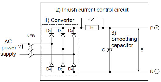
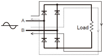
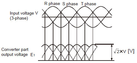
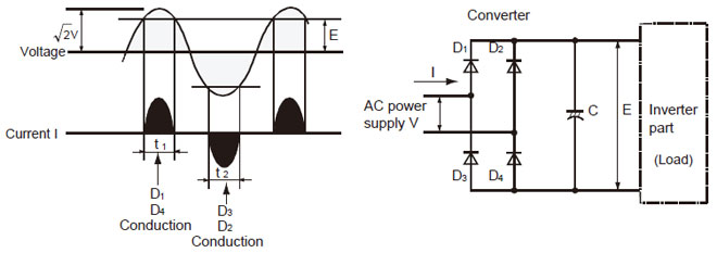
For the AC power line, the system (VFD + motor) is a non-linear load whose current include harmonics (frequency components multiples of the power line frequency). The characteristic harmonics generally produced by the rectifier are considered to be of order h = np±1 on the AC side, that is, on the power line (p is the number of pulses of the variable frequency drive and n =1,2,3).Harmonics Thus, in the case of a 6 diode (6 pulses) bridge, the most pronounced generated harmonics are the 5th and the 7th ones, whose magnitudes may vary from 10% to 40% of the fundamental component, depending on the power line impedance. In the case of rectifying bridges of 12 pulses (12 diodes), the most harmful harmonics generated are the 11th and the 13th ones. The higher the order of the harmonic, the lower can be considered its magnitude, so higher order harmonics can be filtered more easily. As the majority of VFD manufacturers, Iacdrive produces its low voltage standard variable frequency drives with 6-pulse rectifiers.

The power system harmonic distortion can be quantified by the THD (Total Harmonic Distortion), which is informed by the variable frequency drive manufacturer and is defined as:

THD = √(∑h=2 (Ah/A1)2)

Where
Ah are the rms values of the non-fundamental harmonic components
A1 is the rms value of the fundamental component

The waveform above is the input measured current of a 6-pulse PWM variable frequency drive connected to a low impedance power grid.

Normative considerations about the harmonics
The NEMA Application Guide for variable frequency drive systems refers to IEEE Std.519 (1992), which recommends maximum THD levels for power systems ≤ 69 kV as per the tables presented next. This standard defines final installation values, so that each case deserves a particular evaluation. Data like the power line short-circuit impedance, points of common connection (PCC) of variable frequency drive and other loads, among others, influence on the recommended values.

Voltage harmonics
Even components 3%
Odd components 3%
THDvoltage 5%

The maximum harmonic current distortion recommended by IEEE-519 is given in terms of TDD (Total Demand Distortion) and depends on the ratio (ISC / IL), where:
ISC = maximum short-current current at PCC.
IL = maximum demand load current (fundamental frequency component) at PCC.

Individual Odd Harmonics
(Even harmonics are limited to 25% of the odd harmonic limits)
Maximum harmonic current distortion in percent of IL
ISC/IL <11 11<h<17 17<h<23 23<h<35 35<h TDD
<20 4 2 1.5 0.6 0.3

Negative sequence

Negative sequence will not cause a physical rotation. This component creates a field which, though not strong enough, tries to counter the primary field, An increase in this component will cause the motor to overheat due to the opposition. a physical rotation is not likely to occur.

Negative sequence currents are produced because of the unbalanced currents in the power system. Flow of negative sequence currents in electrical machines (generators and motors) are undesirable as these currents generates high temperatures in very short time. The negative sequence component has a phase sequence opposite to that of the motor and represents the amount of unbalance in the feeder. Unbalanced currents will generate negative sequence components which in turn produces a reverse rotating filed (opposite to the synchronous rotating filed normally induces emf in to the rotor windings) in the air gap between the stator and rotor of the machines. This reverse rotating magnetic field rotates at synchronous speeds but in opposite direction to the rotor of the machine. This component does not produce useful power, however by being present it contributes to the losses and causes temperature rise. This heating effect in turn results in the loss of mechanical integrity or insulation failures in electrical machines within seconds. Therefore it is undeniable to operate the machine during unbalanced condition when negative sequence currents flows in the rotor and motor to be protected. Phase reversal will make the motor run in the opposite direction and can be very dangerous, resulting in severe damage to gear boxes and hazard to operating personnel.

Why companies don’t invest in variable frequency drive control

Investing in energy efficient variable frequency drives (VFD) seems like an obvious path to cutting a company’s operating costs, but it is one that many companies ignore. This article explores some possible reasons for this reluctance to invest in VFD.

There is a goldmine of savings waiting to be unlocked by controlling electric motors, but the reluctance to take advantage of this is a very puzzling phenomenon. Motors consume about two thirds of all electrical energy used by industry and cost 40 times more to run than to buy, so you would think optimizing their efficiency would be a priority. The reality is that this good idea is not always turned into good practice and many businesses are missing out on one of the best opportunities to boost profits and variable frequency drive growth.

It might surprise you to learn that your average 11kW motor may cost about £500 to buy but £120,000 to run at 8,000 hours per year over a 15-year lifetime (and that isn’t even accounting for inevitable increases in energy prices). It’s worth considering the payback on any investment in motor control that will reduce this significant running cost, such as using VFDs to control speed, or implementing automated starting and stopping when the motor is not needed. Payback times can often be less than 1 year and, of course, the savings continue over the lifetime of the system, particularly as energy costs rise.

The question that often arises when I talk about this subject to people is: “If the savings are so great, why don’t more people do this?” It would appear to be something that fits into the nobrainer category, however there are three main barriers to the wider uptake of motor control with variable frequency drive, none of which should stop common sense from prevailing – but all too often they do.

The first barrier is a lack of awareness of how much energy is being consumed, and where, in a business. A surprising number of companies do not have a nominated energy manager, still less have energy management as a dedicated job function or have a board member responsible for this significant cost. Those that do measure their energy consumption often have a financial rather than technical bias, so solutions tend towards renegotiating supply contracts, rather than reducing consumption.

The second barrier stems from the economic climate and the level of uncertainty about future events and policies. Businesses are still reluctant to invest in improvement projects, despite short payback periods and the ongoing benefits. The short-term focus is on cutting costs, not on spending money, even to the detriment of future growth. This make-do-and-mend attitude is often proudly touted as a strength, but it is ultimately a false economy. Saving money by cutting capital budgets, reducing staff and cancelling training is damaging to a business and to morale, making it difficult to grow again when the opportunity arises. Saving money by reducing energy consumption makes a business more competitive, while keeping hold of key skills and resources.

The third barrier is a focus on purchase cost, rather than lifetime cost. Whenever a business invests in a machine, a production line or a ventilation system, you can be sure they will have a rigorous process for getting several quotes, usually comparing price, with the lowest bid winning. Something that is not often evaluated is the lifetime energy cost of the system. Competing suppliers will seek to reduce the capital cost of the equipment but without considering the true cost for the operator, including energy consumption. What if the cost of automation and motor control added £700 to the purchase cost? Many suppliers will consider cutting this from the specification. But what if that control saved £1,400 per year in energy? It co

Variable frequency drive saves energy on fans

Like pumps, fans consume significant electrical energy while serving several applications. In many plants, the VFDs (variable frequency drives) of fans together account for 50% to 60% of the total electricity used. Centrifugal fans are the most common but some applications also use axial fans and positive-displacement blowers. The following steps help identify optimization opportunities in systems that consume substantial energy running the fan with VFDs.

Step 1: Install variable frequency drive on partially loaded fans, where applicable. Any fan that is throttled at the inlet or outlet may offer an opportunity to save energy. Most combustion-air-supply fans for boilers and furnaces are operated at partial loads compared to their design capacities. Some boilers and furnaces also rely on an induced-draft fan near their stack; it must be dampened to maintain the balanced draft during normal operation. Installing VFDs on these fans is worthy of consideration.

Similar to centrifugal pump operation, the affinity law applies here. Because constant-speed motors consume the same amount of energy regardless of damper position, using dampers to maintain the pressure or flow is an inefficient way to control fan operation.

Step 2: Switch to inlet vane dampers. These dampers are slightly more efficient than discharge dampers. When a VFD can’t be installed to control fan operation, shifting to inlet vane control could provide marginal energy savings.

Step 3: Replace the motor on heavily throttled fans with a lower speed one, if applicable. Smaller capacity fans with high-speed motor VFDs operate between 25% and 50% of their design capacity. Installing a low-speed motor VFD could save considerable energy.

For example, a 2,900-rpm motor drove a plant’s primary combustion air fan with the discharge side damper throttled to about 75–80%. Installing a VFD on this motor would save considerable energy, but we recommended switching to a standard 1,450-rpm motor. This was implemented immediately, as 1,450-rpm motors are readily available. With the lower-speed motor, the damper can be left at near 90% open; the fan’s power consumption dropped to less than 50% of the previous level.

Step 4: Control the speed when multiple fans operate together. Fans consume a significant amount of energy in industrial cooling and ventilation systems. Supply fans of HVAC systems are good candidates for speed control by variable frequency drives, if not already present.

Step 5: Switch off ventilation fans when requirements drop. Ventilation systems usually run a single large centrifugal fan or several axial exhaust fans. A close look at their operation may indicate these fans could be optimized depending upon the actual ventilation needs of the building they serve.

Recently, we surveyed a medium-sized industrial facility where 26 axial-type exhaust fans were installed on the roof of one building. All fans were operating continuously, even though the building had many side wall openings and not much heat generated inside. To better conserve energy, we suggested the 26 fans be divided into four groups with variable frequency drives controlled for each group. As a result, energy consumption for the fans dropped by about 50%, as only the required fan groups now are switched on.

At another industrial site, the exhaust fan of a paint booth ran continuously but paint spraying was scheduled only about 50% of the time. Modifying fan operation with variable frequency drive and delayed sequencing saved energy.

Pumps and fans are the most common energy-consuming devices