Category: Iacdrive_blog

Variable Air Volume System Optimization

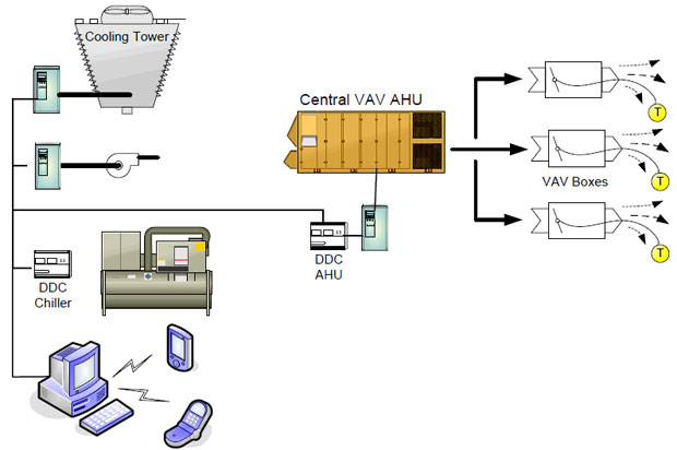
Variable Air Volume Systems (VAV) can be optimized to increase energy savings by maximizing the efficiency of the equipment at part-load conditions. The goal with the optimization strategy is to run each subsystem (chiller, cooling tower, Airhandler, etc) in the most efficient way possible while maintaining the current building load requirement.

VAV System Optimization

As each Variable Air Volume terminal controls the space temperature – based on flow – the “worst case” zone can easily be identified by an automation system. The supply fan speed can be reduced by resetting the static pressure (see following page). As the load drops and the fan meets a preset minimum flow, the system resets the air temperature up, so less chilled water is needed. In a variable flow chiller system, this reduces pumping energy.

If the system load continues to drop, the system will reset the chiller supply water temperature upward which will then reduce the energy requirements of the chiller. Changes in the chiller head pressure and loads can then reset the cooling tower fan speed.

The key to optimizing the system operation is communication and information sharing through the entire system equipment. With the reduced cost of variable frequency drives and Building Automation Systems, (BAS) complete system optimization can be implemented as a cost effective option.

In VAV systems where the individual VAV boxes and the AHU are on a building automation system, additional savings can be achieved by implementing static pressure reset. The static pressure sensor in a VAV system is typically located two-thirds of the way downstream in the main supply air duct for many existing systems. Static pressure is maintained by modulating the fan speed.

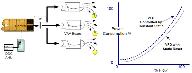
When the static pressure is lower than the setpoint, the fan speeds up to provide more airflow (static) to meet the VAV box needs, and vice-versa. A constant set point value is usually used regardless of the building load conditions.

Under partial-load conditions the static pressure required at the terminal VAV boxes may be far less than this constant set point. The individual boxes will assume a damper position to satisfy the space temperature requirements. For example, various VAV box dampers will be at different damper positions, (some at 70% open, 60% open, etc) very few will be at design, ie 95% -100% open.

RESET STRATEGY
Essentially, resetting supply air static pressure requires that every VAV box is sampled with the static reset set to the worst case box requirement. For example, each box is polled, every 5 minutes. If no box is more than 95% open, reduce duct static pressure set point by 5%. If one or more boxes exceed 95% open, increase static pressure set point by 5%.

With a lower static set point to maintain, fan speed reduces. The result is increased energy savings in the 3 to 8% range. See figure below. If the BAS system is already installed, implementing this strategy is relatively free.
Variable Air Volume System energy savings

Power factor of a generator connected to national grid

Q: What should be the power factor of a generator connected to national grid in order to have maximum stability? Whether it should be high or low?

Steady State Stability:
1. National grid is like a infinite bus for an average size Generator. We can observe stable operation of generator within its capability limit for all ranges of power factor for infinite time , irrespective of power factor.
2. Observe the load cycle, The generators operate in overexcitation mode (lagging pf) during the day & during night ,when transmission lines generate enough reactive the same generators operate stable in underexcitation mode (leading pf).
3. Therefore as long as there is no instance of large disturbance, we can observe stable operation of generator within its capability limit for all ranges of power factor.

Transient Stability:
1. Depends upon the initial condition of the generator operation (see on Power vs Sin-delta plot)
2 The level of power thrown-off causing the disturbance & Equal area criterion of the energy balance & Inertia.
3 During transient/disturbance, the stability is ensured better if the angle delta (rotor angle or power angle) is small, meaning the amount of store energy in the rotating system is high. Theoretically this means delta angle =0 to have robust stability, but it is practically impossible to have power generation at that value.
4 In order to have maximum stability & power generation simultaneously , the value of rotor angle has to be non zero , on positive side. (negative means motor operation).
To Conclude : It means over-excited mode.(lagging pf ). Many colleges in discussion chain above have written near about 0.9 – 0.94 lagging . They are correct.

Frequency Inverter Direct Digital Control

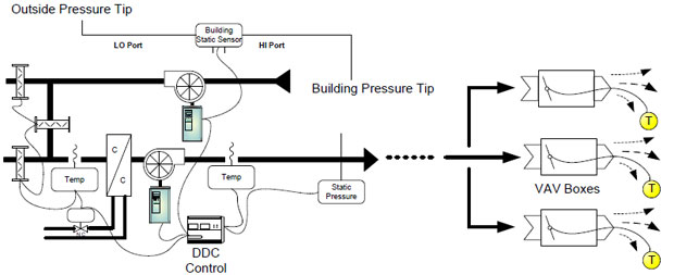
Modulating Supply & Return Fans are used as a means of providing proper variable air volume (VAV) control as well as building pressurization. Many such VAV systems are still largely pneumatic with static to the downstream boxes being maintained by inlet guide vanes. To provide increased energy savings and energy comfort, these systems can be easily converted to frequency inverter fan control of the supply and return fans and Direct Digital Control (DDC) to coordinate any increased energy saving strategies. Figure 1 shows such a system.

Frequency Inverter Direct Digital Control

To increase energy savings, the DDC controller can be programmed to reduce the flow from the return & supply fans for short periods of time. Coordinated with the building pressurization system, any temporary loss of space temperature may be avoided.

In Figure 1, the supply fan is controlled by the duct static pressure sensor, via the DDC, while the outside air and mixed air dampers are optimized to provide economizer control.. The return fan is modulated to stabilize building pressure at a slight positive. For simple supply and exhaust systems the building pressure and static pressure sensors may be connected directly to the frequency inverter with an internal PID controller.

Typical Energy Savings are realized from converting pneumatic (or electromechanical) control to DDC control with frequency inverter in the following ways:

  • Locking inlet guide valves mechanically open to allow the frequency inverter to fully modulate the fans.
  • Free cooling by accurately modulating the economizer dampers and sequencing the mechanical equipment.
  • Controlling static and resetting the static pressure during short periods of time.
  • Accurate building pressurization.
  • Implementing other energy saving measures which include supply air reset, and night purge routines.

CONTROL CONSIDERATIONS

  • Placement of the indoor static pressure sensor is important as it should provide a stable signal. Entrances, dock, and other areas where large , sudden static pressure changes may occur should be avoided.
  • The outside reference static tip should be shielded from wind and rain.
  • When the exhaust fan is frequency inverter controlled, consider a 2-position air damper to prevent the outside air from entering the building (infiltration) when the exhaust fan is off or a very low speeds.
  • For simple VAV systems, consider using frequency inverters with built in PID controls such as the Iacdrive frequency inverters.. This minimizes hardware and installation costs. Static sensors provide a 0-10vdc control signal directly to the frequency inverter.
  • Duct mounted static pressure sensor should be mounted 2/3 of the distance of the distribution system.

Current transformer selection

When you want to select current transformer with appropriate rated power for your power system, you need to consider that value of rated power of selected current transformer should be higher from sum of values of load and Joules’ losses which are a consequence of flow current through conductors which connect current transformer with relay.

So, if you have a long distance between current transformer and relay, then you need to consider one of two following manners for solving this problem:
1. replacing existing current transformer with current transformer with higher power,
2. replacing existing conductors with conductors with lower cross-section.

This solution is a consequence of necessity for reducing of Joules’ losses which are a consequence of flow current through conductors which connect current transformer with relay. If you have conductors whose value of rated current is 5A, you will have Joules’ losses P=R*I^2=R*5^2=25*R. Otherwise, if you have conductors whose value of rated current is 1A, you will have Joules’ losses P=R*I^2=R*1^2=R.
On this way, Joules’ losses in your selected conductors will be reduced 25 times and selected current transformer will be unloaded by reducing additional load.

Rotary Tube Furnace Efficiency

There are many factors that govern the performance of rotary tube furnaces. A direct fired rotary unit has a potential for much higher thermal efficiency due to the direct contact of the hot gases with the material in process. Cement kilns are the most common large scale unit operation with direct fired units. Any articles you find on this will be helpful. Thermal efficiency can be estimated by dividing the inlet temperature minus the outlet temperature by the inlet temperature minus the ambient temperature in absolute scales either Rankine or Kelvin. Then there is the issue of co-current versus counter-current firing and heat recovery from the hot material and the exit gas for which standard designs are available. Indirect fired rotary kilns have heat transfer limitations due to the thickness and alloys needed for high temperature calcination >500 C. There is no simple way to measure the equivalent of the inlet and outlet temperatures on a direct fired unit. There are simply exit gas temperatures from each zone and an approximate shell temperature on the hot side of the shell which is lower than the zone exit gas temp. These are useful for control purposes and consistent operation. The higher the temperature the material requires to achieve conversion the higher the shell side fired temperature has to be to provide the delta T necessary to drive heat through the shell into the material zone.

Some materials further limit heat transfer by adhering to the inside of the shell and acting as an insulator! This requires trial and error application of “knockers” at the ends of the shell or sometimes internally secured chains that bang around and knock the adhering material loose. This is a potential nightmare as the learning curve to install chains so that the securing lugs and the chains themselves will stay attached for acceptably long service before failing and ending up in the take off conveying equipment with usual breakage and downtime is an uncertain one. From Perry’s one can find thermal efficiencies for indirect fired rotary’s given as less than 35%. The bed fill can be 10-30% depending on the heat demand of the material and the heat transfer limitations. You will want to have real time gas usage metering on the burners so that you know the theoretical energy input. From that you can subtract the theoretical heat needed to complete your reaction and compare that to the input to see how efficiently you have used the energy input.

The few large high temperature direct fired rotary kilns I have seen had view ports for measuring the local wall temperatures by optical pyrometer. It can be a challenge to get a protected thermocouple sheath down into the moving bed for an actual bed temperature and even just to hang it in the gas streams at the outlet or inlet area. See if you can contact cement kiln suppliers for some configurations of temperature sensing elements for your application. Bed fill effects on heat transfer are related to several parameters. Above ~500 C gas and refractory liner temperatures, the main heat transfer mode will be radiative as far as the surface of the bed material. Within the bed it will be conduction and some convection at the surface. A thin bed will reach max. temperature in shorter time, but this reduces through put for a given gas temperature. If you increase bed fill to increase production you will have to increase the firing temperature and the outlet temperature will probably increase lowering your thermal efficiency. This becomes a trade off between production rate and energy efficiency. Countercurrent firing usually maintains the highest driving force for heat transfer along the bed and gives the highest temperature of the bed just before exit of the bed material.

Perry’s may have a useful section on direct fired rotary kilns and lime or cement manufacturing references may help you as well. Please make sure lead emissions to air are properly captured

Calculate Capacitors Power

In general, to calculate the necessary Power of Capacitors, we can use the following formula:

Qc = P ( tgφ1 – tgφ2 )

where :
– Qc : the Power of Capacitors.
– P : the total Power of Loads that are running during normal working.
– tgφ1 : the tangent of φ1 ( the angel between current & voltage before compensation )
– tgφ2 : the tangent of φ2 ( the angel between current & voltage after compensation )

In all cases, we should take into consideration the following points :
1- It will be better to oversize the calculated Qc by ” 10 to 15% “.

2- Be careful when compensate the PF of a Motor to avoid the Over-excitation case, but we can verify it by using the following formula : Qc (motor) = 2 x P (1 – Cos φ ), where :
– P : the Motor’s Power.
– Cos φ : the PF of the motor before compensation.

3- After calculation of Qc, the choosing of Capacitors type will be done according to the Harmonic Distortion percentage. Noting that in some case where the Harmonic Distortion percentage is high, we should use ” Detuned Reactors ” with Capacitors, and when this percentage is too high, we can’t install the Capacitors before minimizing or eliminating the harmonics that their percentages are too high.

Can I operate a 50Hz transformer at 60Hz power supply?

Well first let get one thing straight for transformers: the higher the line frequency, the lower the core (iron) losses! The core power loss are proportional to kf*B^2 approximately for any machine, dynamic or static. But transformers are self-excited static machines, meaning the flux density B is reverse proportional to the line frequency, therefore Pcoreloss = kB^2*f=k*(1/f)^2*f=k/f… so the higher f, the lower the losses. However, increasing the frequency also increases the magnetizing inductance – lowering the magnetizing current. For if you increase the frequency you may want to increase the voltage. But of course this is not usually practical, as line voltage of 60Hz systems is usually lower than those of 50Hz systems. So operating a 50Hz motor at 60Hz should be safe, but may result in higher voltage drop because of lower magnetizing current and because of higher leakage inductance (the series inductance).

It is true that the higher the frequency, the higher the hysteresis (and eddy current) losses will be. But is it a common misconception to assume higher power losses when frequency increases in a transformer. Simply because the hysteresis losses depends not only on frequency, but on the max magnetic flux density as well (Bmax^2). The flux density is reversely proportional to the line frequency, which eventually causes lower core losses as you raise the frequency. This holds true for low and mid frequency ranges. For higher frequencies, skin effect and eddy currents dominates, so the picture may be different. However, iron core transformers do not operate in such high frequencies. We use ferrite core instead. In a practical transformer model, the core losses are represented by a parallel resistor (Rc). The resistor’s value is linearly dependent of the line frequency (Rc=k*f), and the core losses are given by Pc=U^2/Rc… Of course this model is limited to mid-low frequencies…

Electrical drives for off-highway vehicles

I’ve seen some attempt of electrical driven prototypes in the field, but is still not an enough big sector that let you find specific literature. Excluding the large dumpers for mining, probably the only machine that is built in series is D7E from CAT.

One of largest engineering challenge that you will face on a similar application, is the cooling to the power electronic. You can consider that you will have to dissipate 3-5% of the power that your driver is processing and the max temperature of IGBT’s is not so far from the max temperature in that your vehicle can operate. A small temperature delta, mean a large heat exchanger and/or pretty high speed of air through it. (That with all the problems related to that). A possible solution is liquid cool the IGBT’s mounting them on the aluminum plate. You can’t use the engine cooling fluid because it too warm, but you may can use hydraulic oil (that should never get warmer of 55C).

If you are thinking to expand some gas from the AC, please take in account the possible condensation issues (your voltage on the DC bus can arrive around 800V when the vehicle is breaking, you do not want condensation around). Using SR motors is opening another challenge. For take max advantage of the technology, you want the motor spinning pretty fast (motor get smaller for same size of rotor and with that design, no problems retaining magnets). That means use high ratio gears. In off road vehicle are often used planetary gears because they are compact and cheap. As soon you rise the input speed, the efficiency of those kind of gears drop because you incur in hydrodynamic loss (for a series of problems that are connected to the level of oil that you need to keep in the gear housing). Probably if you are using an SR motor, you want consider to use an angular stage like first reduction after the motor.

I’m not too sure if I would use a battery like energy storage. Batteries take time for convert from electrical to chemical. Most of the braking will happen in a short time so you will end up burning most of the regenerated energy trough a braking resistor (the DC bus can’t go up to infinite about voltage). If you are driving a dozer that has a very low efficiency (most of the vehicle kinetic energy will be burnt in the tracks etc. and very little will arrive to the SR motor to be regenerate), probably the regeneration is not too important, on other vehicle is maybe more important so look to capacitors or flywheels for storage is probably more appropriate.