Archives: FAQs

Can I use an AC drive on a servo motor?-

If you are looking to use a standard, plain AC variable frequency drive for a servo I suggest you will be out of luck. Servo motors typically require a different type of output – not a V/Hz or even vector type output PWM output waveform.

Before you buy an AC drive said to be suited for servo motor, you might want to get that in writing and find someone that will stand behind the claim. If there is a cost savings to using an AC VFD drive to run your servo motor you may want to use the extra cash to get a factory technician to do a startup
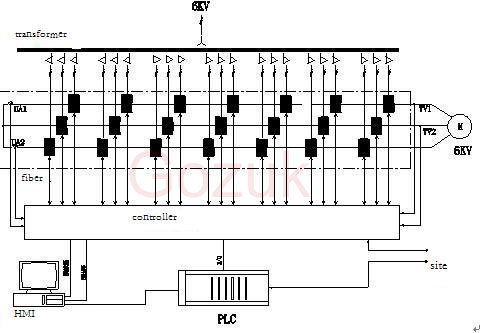
How to choose an AC drive?

When selecting AC drive size and power ratings, consider the operating profile of the load it will drive. Will the loading be constant or variable? Will there be frequent starts and stops, or will operation be continuous?

Consider both torque and peak current. Obtain the highest peak current under the worst operating conditions. Check the motor FLA, which is located on the motor’s nameplate. Note that if a motor has been rewound, its FLA may be higher than what’s indicated on the nameplate.

Don’t choose the AC drive size according to horsepower ratings. Instead, choose the AC drive to the motor at its maximum current requirements at peak torque demand. The AC drive must satisfy the maximum demands placed on the motor.

What’s an ideal Variable Frequency Drive?

The ideal ac motor speed control offers a combination of digital variable frequency drive (VFD) with some programming capabilities. The most common VFDs control functions we’re asked about are speed, torque, acceleration ramp, deceleration ramp, run, stop, direction, over-current protection, and speed read-out capability. Many of our customers want the “all-in-one” solution as well; eliminating components and simplifying set-up is the key of an ideal variable frequency drive.

What is AC Drive Reconstruction for Oil Industry Company

Reconstruction purpose
In order to lower production cost and power consumption, variable frequency technology should be adopted.

By utilizing low voltage AC drive, the plant has gained considerable energy saving effect and maintenance experience. With maturity of medium voltage AC drive, we utilize this technology outcome to medium voltage motor. We reformed for three fans.

Parameters of fans

Fan Rated voltage Rated current Rated power Power factor Rated speed
PA fan 6000V 131A 1120kW 0.85 1490r/min
SA fan 6000V 94A 800kW 0.85 1490r/min
1# ID fan 6000V 61A 500kW 0.85 990r/min

Reconstruction scheme
1. AC drive selection
After comparing and analyzing, the plant selected Iacdrive AC drive eventually.

2. Main circuit
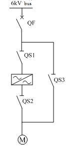
We decided to adopt “one drive one” scheme due to importance of fan. That is, one AC drive drives one motor of fan. In order to improve reliability and safety, we add bypass circuit. Please see the figure.

Iacdrive|AC_drives|variable_frequency_inverter|VFDs|confverter|elevator

QF is vacuum breaker. QS1, QS2 and QS3 are medium voltage isolator. Medium voltage AC drive is between QS1 and QS2. QS3 is bypass switch. When motor needs to run in variable frequency, open QS3 and close QS1, QS2, then close QF. When motor needs to run in direct on line, open QS1, QS2, close QS3 and then close QF. In this way, motor can run in direct on line during AC drive downtime or maintenance.
Above scheme is typical manual scheme. QS2 and QS3 interlock in mechanism and they cannot close simultaneously.

In order to realize fault AC drives protection, AC drive sends trip command when it faults seriously and link trips medium voltage breaker to make AC drive off power. In the meantime, three switches interlock  electrically with QF. Only when breaker is off, can personnel operate switch, which ensures safety.

3. Control scheme
According to actual state, we adopt three control schemes. They are DCS close loop control, DCS open loop control and local control.

4. Cooling scheme
Principle of AC drive is to rectify AC to DC and invert DC to AC. During this course, electric components emit heat (2%). The heat causes equipment temperature up and damages equipment. In order to ensure stable work of AC drive, the heat must be dissipated outside. So cooling scheme is very important. After researching carefully, we adopt the most effective and easiest scheme—air cooling. Install air duct on top of AC drive. The duct discharges the heat outside. The scheme only needs a duct without other device, so it is simple and reliable with few failure factor. Make full load test at 40℃. Max temperature of AC drive reaches to 68℃. Compared with max design temperature-rising, the result is ideal.

How to select the AC drives cables.

In order to better understand the variables involved with the cables that are a key part of any AC drive system and to formulate a useful guide to cable selection, the most commonly recommended cables for AC drive applications have been studied by Iacdrive, in both a lab and working application. Some wiring methods were not examined, however, such as THHN building wire in conduit, since their use has been shown to have detrimental effects, as outlined in other studies. An exception to this exclusion was the use of PVC-Nylon insulated, PVC jacketed tray cables. These cables are the most commonly-installed type of industrial control cable, and though they are often misapplied for use in AC drives applications, they were included in the tests for purposes of comparison. The PVC-Nylon designs (PVC-Nylon/PVC Type TC and PVC-Nylon/PVC Foil Shield Type TC) were evaluated in both unshielded and foil shielded versions.

How much is energy saving with variable frequency drive

Most companies accept that their energy bills are too high and most businesses would like to lower them. However, awareness of how this can be achieved is actually surprisingly poor. There is a genuine disconnect, even in engineering and technology firms, between the people making the buying decisions and the technical staff able to offer the best advice on the right energy saving technologies, such as VFDs (variable frequency drives). Here Iacdrive, the deputy director of Iacdrive responsible for the Association’s variable frequency drive Group, explains why clearer systems thinking at all levels could be the key to solving this conundrum.

Fitting VFDs can result in energy savings of up to (70%) in the right circumstances and, in addition, there can be reduced motor maintenance costs that go hand in hand with this. Furthermore, depending on the sophistication of the VFD, there may be a built in PLC (Programmable Logic Controller) or even built in system diagnostics. A PLC can provide energy savings by turning the motor off at times when it isn’t required, such as in fan and pump applications which might otherwise run all day, even if there are times when they aren’t needed.

What is VFD boosts productivity in automation industries

VFDs boost productivity with the ability to gain precise control of processes. Whether it’s speed, torque, or position control (or any combination), VFDs offer the ability to fine tune and control electrically driven machines to make them more efficient for high volume, high-quality production. Controllability and tuning make machines more adaptable and compatible with changing production materials and processes. VFD also allows easy monitoring of machine production through digital and analog signals as well as serial communication. VFD often reduces energy costs when used to decrease speed or torque, particularly with centrifugal-type loads such as fans or pumps.

Why a DC capacitor is required to connect across the alternator terminals?

Use of a DC cap across alternator terminals is often done to filter alternator whine (noise) caused by voltage ripple, the “AC” component of rectified DC output. When the capacitance is properly installed and matched to the frequency of the noise, it provides a low-impedance path to “divert” the voltage ripple to ground.

What is the problem if I use a 15hp vfd for a 1hp induction motor speed control?

The issue with a drastically over-sized drive is controllability, especially at lower speeds. Accuracy will suffer, because the drive thyristor firing angle will be so low that it will be difficult for the drive software to manage. And if you are concerned about motor protection you will have very little because the normal operating ranges of the motor protection parameters (overload, over-current, etc.) in a 15hp drive are centered on 15hp motor parameters; they are ranges, of course, but you’ll be way out on the low end of these ranges and response will suffer.

What is exactly the difference between AC and DC capacitor in functionality and manufacturing?

In essence, a “capacitor is a capacitor”, although there are differences in design based on topology, type, and materials of manufacture. Sometimes capacitors will carry a dual rating, for AC and DC – the AC rating for a capacitor of the same capacitance is typically much lower than its DC rating (often at least 3-4x less since AC max voltage peak-to-peak is ~2.8x rms), to accommodate the significant heating internal to the cap caused by frequency/alternating polarity. Some manufacturers manufacture AC caps which are essentially two DC caps in series back-to-back; these limit current flow through either cap but their internal resistance is somewhat high, which can lead to eventual break down due to heating as well.